Bei Encoder Wiring Diagram
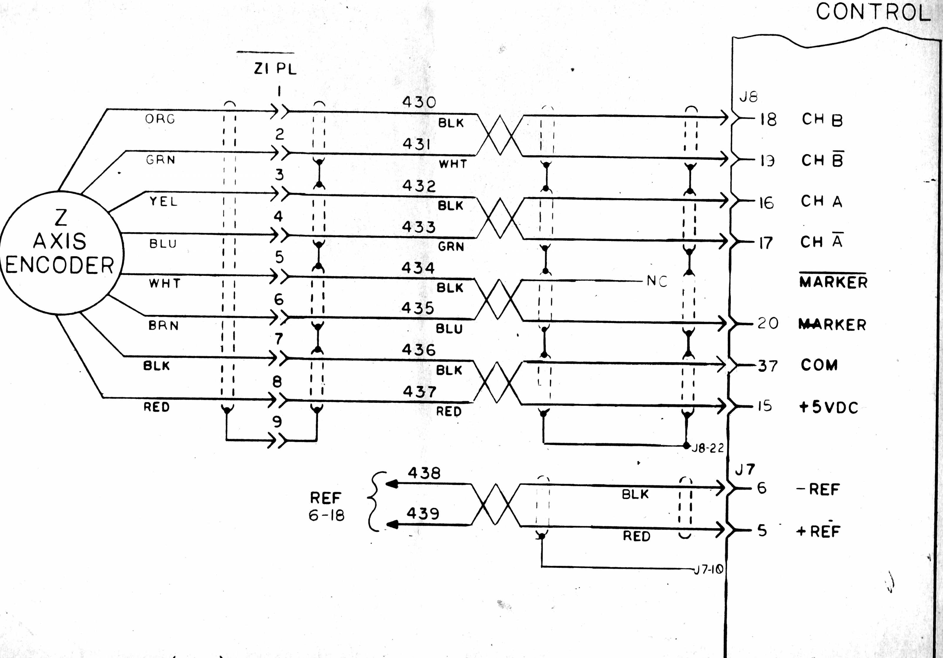
Output output* 1 case grnd. Missing or extra counts electrical • confirm encoder output is compatible with.
As to resolution, you have the natural quadrature count consisting of a pulses per revolution, or using 2 edges for x2 or all four (a+b) edges for x4 quadrature count.
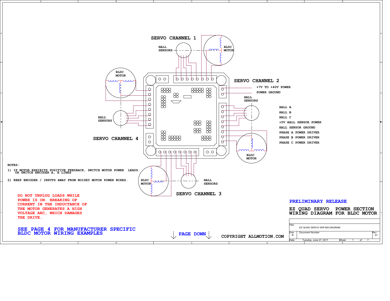
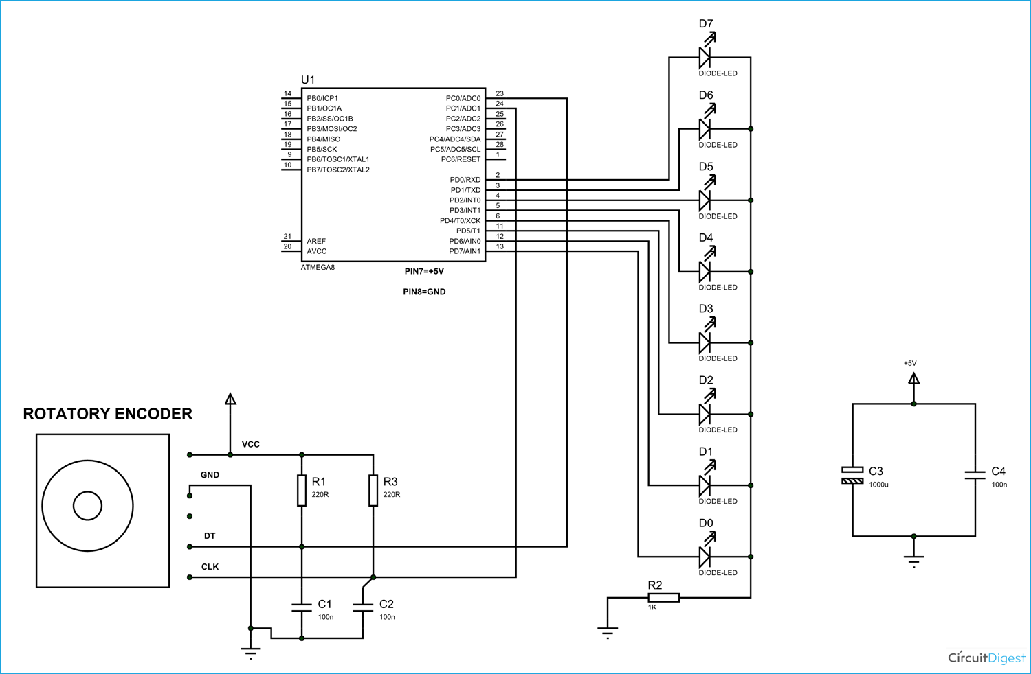
Bei encoder wiring diagram. A wiring diagram is a simplified standard photographic depiction of an electric circuit. Www.encoder.co.uk precision products for every application Certifications the h40 shock proof encoder is available with the following certifications:
Bei h38 explosion proof optical encoder 8 bit terminal incremental gray code pin no. Optical encoders optical encoders optical encoders bei precision optical encoders are available in a variety of configurations and sizes to meet the demands of any customer in any environment. Encoders provide quality measurements and long life when common sense, care, and accurate alignments are provided during installation.
Its hollowshaft design eliminates the need for a flexible shaft coupling. For shaft lengths greater than the maximum engagement allowed, end instructions under "adjusting the encoder to eliminate excess of shaft mounting may still be employed by using a spacer between runout/wobble" are provided if needed. Use of shielded cable is recommended for all encoder installations.
British encoder products company unit 33 whitegate industrial estate wrexham wales, united kingdom ll13 8ug installation and wiring guide phone: Incremental encoders are available in two basic output types, single channel and quadrature. • ensure the encoder has multiple outputs (i.e.
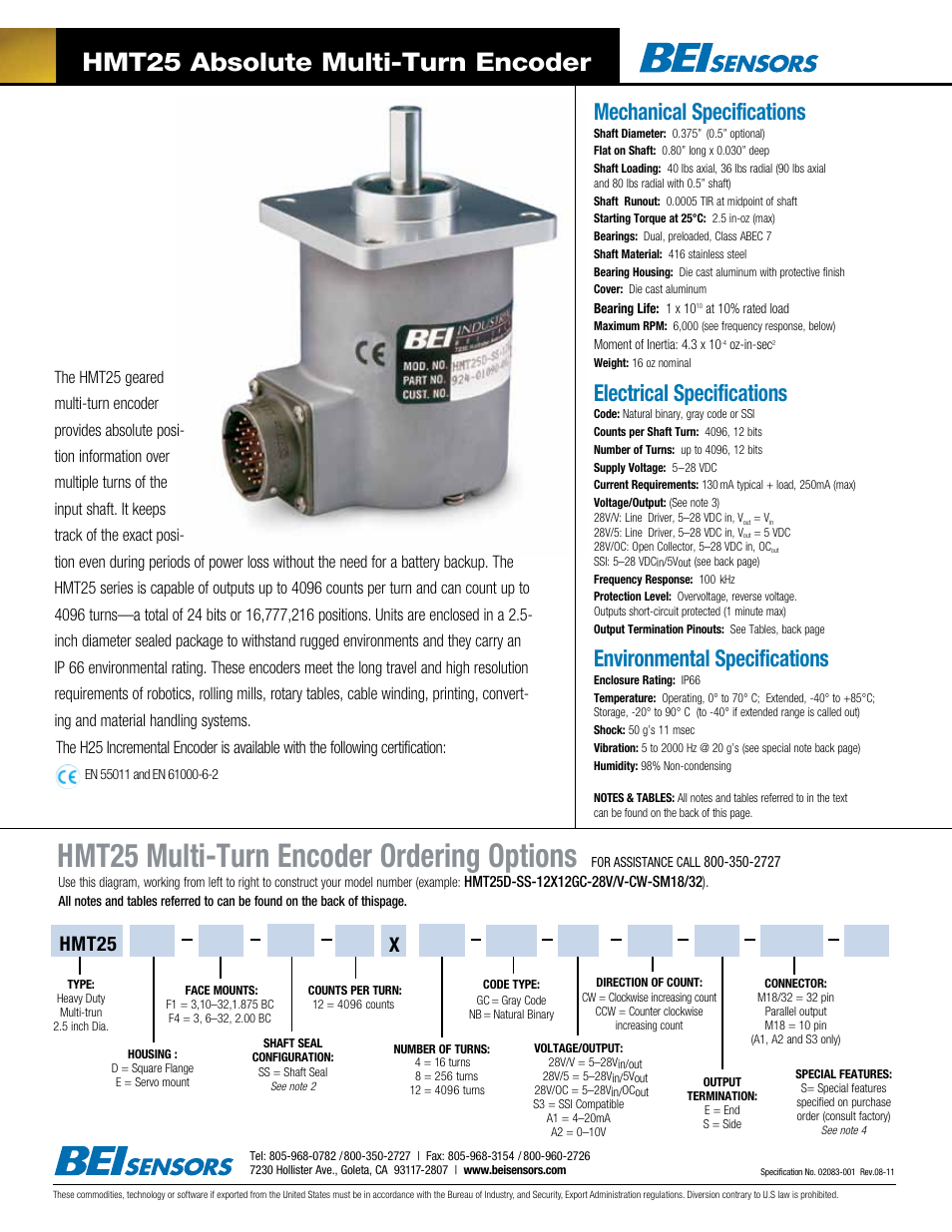
Use this diagram, working from left to right to construct your model number (example: Bei model h25incremental encoder the h25 is the flagship of the bei industrial encoder division product line. Use this diagram, working from left to right to construct your model number (example:
Hs35 express encoders® items highlighted with are standard express encoders and ship in one to three days. The h25 offers features such as emi shielding, 40 lb. Wellborn collection of bei encoder wiring diagram.
Obtaining from factor a to point b. Wiring diagrams avtron standard warranty applies. Rotary shaft encoders respond to rotary movements, while linear encoders are used to monitor longitudinal movements.
The objective is the same: A single channel encoder, often called a tachometer, is normally used in systems that rotate in one direction only, and require simple position and velocity information. Rotary encoders are sensors which convert a movement into an electrical signal.
33 sew eurodrive motor wiring diagram. It was designed from the ground up for the industrial machine tool marketplace. Read 8 pin ice cube relay wiring diagram gallery.
Automationdirect, types of encoders and decoders with truth tables, bei encoder wiring diagram sample wiring diagram sample, encoder wiring diagram entries forum industry, wiring encoder on my plc entries forum industry, 8 3 encoder logic diagram best place to find wiring and, rotary encoders diagram wirings, 4 2 encoder logic Diagram bei encoder wiring diagram full version hd quality wiring diagram diagramland andreapendibene it. Quadrature encoders have dual channels (a and b), phased 90 electrical degrees apart.
Literally, a circuit is the course that enables electrical power to circulation. Ac condenser fan motor wiring diagram 4 wire beautiful for new 7 fan motor electric cooling fan electric fan Rms001 draw wire encoder ifm electronic.
Use this diagram, working from left to right to construct your model number (example: It reveals the parts of the circuit as streamlined forms, and the power and signal connections between the gadgets. All notes and tables referred to can be found on the back of this page.
Encoder wiring schemes can be unique to each encoder and one should follow the diagram or pinout designated on the encoder datasheet. The loads applied to the encoder shaft must be in accordance with the specificatios of this device. The dynapar brand series hs35 sealed hollowshaft encoder is designed for easy installation on motor or machine shafts.
If rotary encoders are coupled with mechanical power transmission devices, such as rack and pinion drives, measuring. 11) connect cable as shown in wiring diagram. Bei encoder wiring diagram may 6, 2020 by larry a.
Mounting the encoder wiring the encoder • never connect or disconnect the encoder connector or wiring while power is on. Direction is detected by referng to the status of a pulse compared to b, iow a would be the amount of pulses and the 1 or 0 level of b detects direction.

Encoder Wiring Diagram Wiring Diagram & Schemas
Encoder Wiring Diagram Wiring Diagram & Schemas

[BZ_9659] Sew Encoder Wiring Diagrams Free Diagram

Bei Encoder Wiring Diagram Sample Wiring Diagram Sample
Model hs35, Drawworks optical encoder, Figure 1 BEI Sensors HS35 Incremental Drawworks Encoder
31 Heidenhain Encoder Wiring Diagram Free Wiring Diagram Source

[BZ_9659] Sew Encoder Wiring Diagrams Free Diagram

Bei Encoder Wiring Diagram JEBON007

[BZ_9659] Sew Encoder Wiring Diagrams Free Diagram

Bei Encoder Wiring Diagram Free Wiring Diagram
Encoder Wiring on Mesa 7i77 board LinuxCNC

34 Heidenhain Encoder Wiring Diagram Wiring Diagram Database
